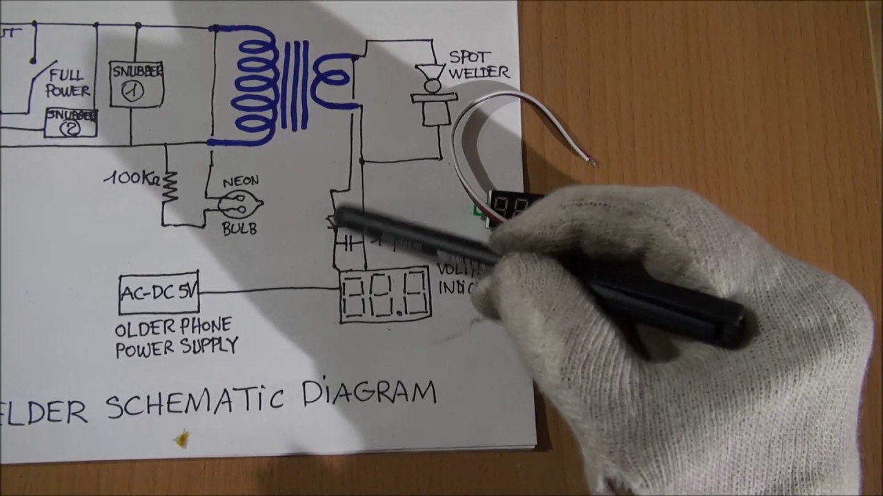
Semi automatic sub arc andor mig welding of butt weld and large fillets which are not accessible to machine driven equipment. A simple resonant circuit ac rectifier inverter arc starter arc main transformer output inductor fig 2.
The impedance of welding transformer may play a role in the process of establishing an arc and controlling the current.

You can find out more Diagram below
Arc welding transformer diagram. International journal of scientific engineering research volume 6 issue 5 may 2015 932. Aims and objectives of the project. Manual stick electrode welding using large diameter electrodes for downhand fillets and short buttsgravity welding is also in this category.
The welding side provides current setting range. Operating principles of a welding transformer. When you are welding the welding current is about 63 a under a 25v arc.
Considering these transients point m. A block diagram of the system 2 circuit operations a block diagram of the system is shown in fig 2. The impedance of welding transformer may be higher than that of the impedance of a general purpose transformer.
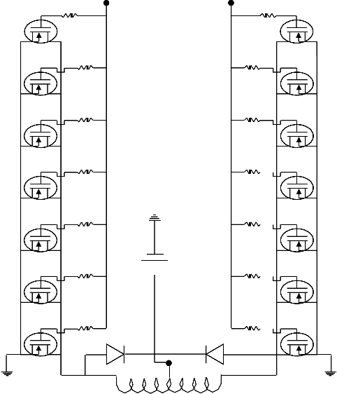
The first stage is a rectifier circuit that converts ac. To solve the problem of weight and size of conventional arc welding machine an inverter circuit was also designed. In this paper the authors designed and constructed 3kva 50 hz single phase arc welding machine using locally available materials.
2348036826053 abstract a two pole type of an ac variable current welding machine was designed and constructed. Large welding transformers are most likely to be designed for three phase input. The welding circuits are properly earthed to protect the welder in the event of a breakdown in the transformer and causing main supply voltage to come into contact with welding side circuit of the transformer.
The weight and size of the transformer of the conventional arc welding machine is much as well as the welding noise. The amount of current can be adjusted by inserting a reactance coil into the circuit. Operating principles of a welding transformer 2.
The inverter provides much higher frequency than 50hz or 60 hz for transformer used in welding. The system block diagram of the inverter arc welding machine project is shown in fig1. So the usage of welding transformer has significant role in welding compared to a motor generator set.
Automatic submerged arc welding of plate butts in downhand position. The first pole is the primary circuit and was design to have a four step coil sa ab. In an ac welding arc the current remains nearly sinusoidal while the voltage is distorted as shown in fig.
Welding transformer working principle and applications characteristics of welding transformer now a days we have many ac power supplies. After reading this article you will learn about 1. Typical output vi characteristic for arc welding supply fig3.
I am taking a course of transformer calculation and rewinding and the course requires that i provide calculations provide all jigs to wind the transformer coils and wind the coils. Requirements of a welding transformer 3. It should be remembered that one 15awg wire limit is 176a under a duty of 10.


0 comments:
Post a Comment