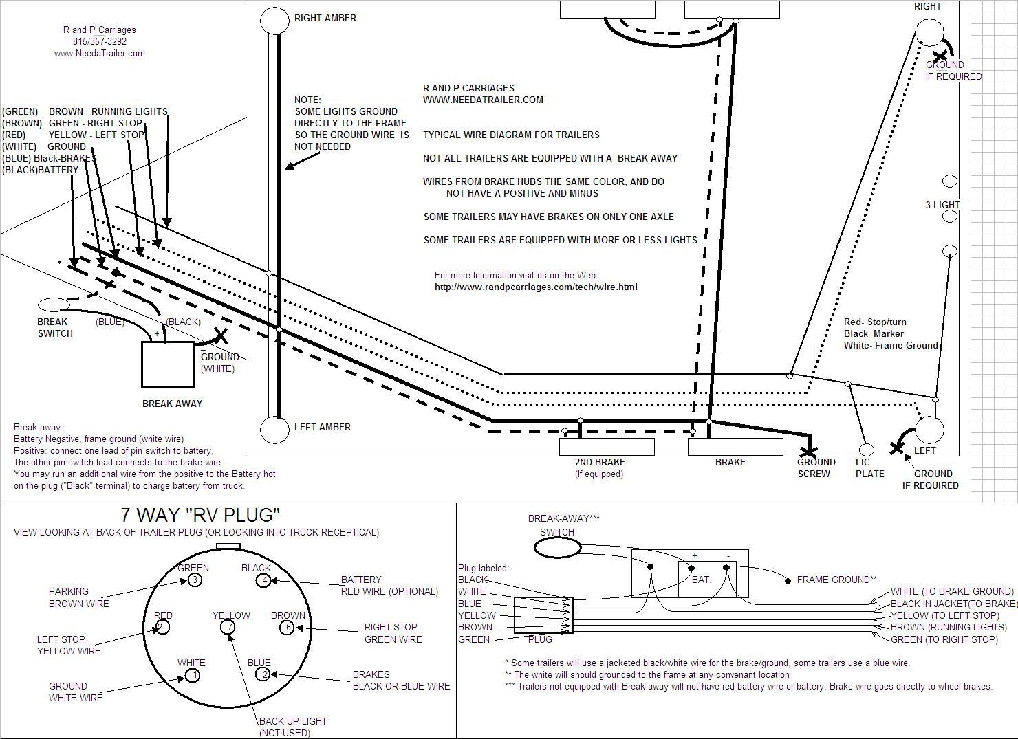
Trailer wiring diagrams trailer wiring connectors various connectors are available from four to seven pins that allow for the transfer of power for the lighting as well as auxiliary functions such as an electric trailer brake controller backup lights or a 12v power supply for a winch or interior trailer lights. 6 way connectors include the basic connection of running lights brake lights turn signals and a ground wire.
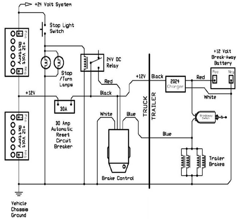
Trailer wiring and brake control wiring.
You can find out more Diagram below
Trailer brake battery wiring diagram. This car is designed not just to travel one place to another but also to take heavy loads. They also have one wire for trailer brakes and one wire for a battery connection. Some trailer builders just connect this wire to the frame then connect the ground from all the other lights and accessories to the frame as well.
Check and install battery and charger into the battery case. Special light and wiring systems need to be installed on your tow vehicle before you can tow any trailer. Bolt breakaway switch to frame of trailer or battery case bracket.
Also it must connect with things if included that use the aux power and back up lights too. 6 way trailer connectors are often used on gooseneck trailers but can be used for other types such as utility boat trailers and 5th wheels. Remove charger and battery from the battery case.
The trailer wiring diagram shows this wire going to all the lights and brakes. Assortment of electric trailer brake wiring schematic. Tail light converters brake control wiring vehicles towed behind a motorhome wiring diagram for common plugs breakaway switches.
Mount battery case securely to frame jack post or other suitable location on trailer. Trailer breakaway wiring diagram 3 wire trailer breakaway switch wiring diagram hopkins trailer breakaway wiring diagram rv trailer breakaway switch wiring diagram people today understand that trailer is a vehicle comprised of quite complicated mechanics. Feed wires out the back then close the top.
Wire per schematic diagram. It reveals the parts of the circuit as streamlined forms as well as the power and signal connections in between the gadgets. A wiring diagram is a streamlined conventional pictorial representation of an electric circuit.


0 comments:
Post a Comment